Product Overview
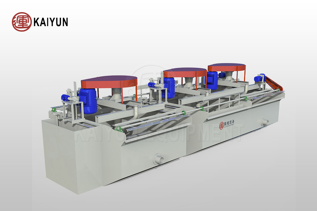
The BF Mechanical Stirring Flotation Machine is an advanced flotation device that integrates pulp suction and self-air absorption functions. Known for its exceptional performance and wide applicability.
The BF Mechanical Stirring Flotation Machine is the preferred tool for the selection of ferrous metals, processing of non-metallic minerals (such as fluorite and talc), and rough and fine selection of non-ferrous metals including gold, silver, copper, iron, tungsten, lead, zinc, tin, molybdenum, nickel, tantalum, niobium, and manganese. Its unique design and efficient operating principle ensure precise mineral separation and enrichment.
Table of Contents

Advantages and Features
Powerful Pulp Circulation
The BF flotation machine’s impeller, constructed with a closed double-cone design, creates a strong pulp circulation that enhances the effective contact between mineral particles and bubbles, thus improving flotation efficiency.
High Air Intake with Low Energy Consumption
The equipment boasts excellent air intake capability, allowing it to draw in sufficient air while consuming less energy. This results in the formation of abundant bubbles, providing an ideal medium for the flotation process.
Integrated Flotation Circuit
Each flotation machine combines air intake, pulp suction, and flotation functions into a complete flotation circuit, eliminating the need for additional auxiliary equipment. The horizontal layout facilitates easy adjustments and optimization of the process flow.
Optimized Pulp Circulation Path
The carefully designed pulp circulation path minimizes coarse sand sedimentation, keeping the flotation tank clean and enhancing the operational efficiency of the equipment.
Intelligent Liquid Level Control
Equipped with both automatic and electronic control devices for the pulp level, the machine can adjust the liquid level height in real-time based on actual conditions, ensuring stable flotation processes and controllable product quality.
Working Principle
The BF flotation machine operates on the principle of impeller rotation. When the impeller spins, the pulp in the upper and lower impeller chambers is subjected to centrifugal force, which is rapidly expelled outward, creating a negative pressure zone within the chambers. This causes the pulp above the cover plate to be drawn through the circulation holes in the cover plate into the upper impeller chamber, forming an upward circulation of the pulp.
Simultaneously, as the lower impeller expels the pulp, the pulp below it is replenished towards the center, establishing a downward circulation. Air is introduced into the upper impeller chamber through the air intake pipe and central cylinder, where it mixes with the incoming pulp to generate a large number of fine bubbles.
These bubbles are evenly dispersed in the tank under the stabilizing effect of the cover plate and combine with the mineral particles in the pulp to form mineralized bubbles. The mineralized bubbles rise to the froth layer due to buoyancy and are scraped off by the scraper, resulting in the froth product of the flotation process.
The entire flotation process is accomplished through the coordinated action of key components such as the impeller, cover plate, main shaft, central cylinder, and tank body in the BF flotation machine, demonstrating the equipment’s high efficiency and intelligent features.
Technical Parameters
| Model | Volume (m³) | L*W*H (mm) | Impeller Diameter (mm) | Impeller Peripheral Speed (m/s) | Air Intake (m³/m²-min) | Motor Model | Motor Power (kw) | Capacity (m³/min) | Single Tank Weight (kg) |
| BF-0.15 | 0.15 | 550×550×600 | 200 | 6 | 0.9~1.05 | Y112M-6 | 2.2 | 0.06~0.16 | 270 |
| BF-0.25 | 0.25 | 650×600×700 | 250 | 6 | 0.9~1.05 | Y100L-6 | 1.5 | 0.12~0.28 | 370 |
| BF-0.37 | 0.37 | 740×740×750 | 286 | 7.2 | 0.9~1.05 | Y90L-4 | 1.5 | 0.2~0.4 | 470 |
| BF-0.65 | 0.65 | 850×950×900 | 300 | 7.35 | 0.9~1.10 | Y132S-6 | 3 | 0.3~0.7 | 932 |
| BF-1.2 | 1.2 | 1050×1150×1100 | 450 | 7.02 | 0.9~1.10 | Y132M2-6 | 5.5 | 0.6~1.2 | 1370 |
| BF-2.0 | 2 | 1400×1450×1120 | 500 | 7.5 | 0.9~1.10 | Y160M-6 | 7.5 | 1.0~2.0 | 1750 |
| BF-2.8 | 2.8 | 1650×1650×1150 | 550 | 8.06 | 0.9~1.10 | Y180L-8 | 11 | 1.4~3.0 | 2130 |
| BF-4.0 | 4 | 1900×2000×1200 | 650 | 8 | 0.9~1.10 | Y200L-8 | 15 | 2.4 ~4.0 | 2585 |
| BF-6.0 | 6 | 2200×2350×1300 | 700 | 7.5 | 0.9~1.10 | Y225S-8 | 18.5 | 3.0~6.0 | 3300 |
| BF-8.0 | 8 | 2250×2850×1400 | 760 | 7.5 | 0.9~1.10 | Y225M-8 | 22 | 4.0~8.0 | 4130 |
| BF-10 | 10 | 2250×2850×1700 | 760 | 7.52 | 0.9~1.10 | Y225M-8 | 22 | 5.0 ~10 | 4500 |
| BF-16 | 16 | 2850×3800×1700 | 850 | 8.7 | 0.9~1.10 | Y280S-8 | 37 | 8.0 ~16 | 8320 |
| BF-20 | 20 | 2850×3800×2000 | 850 | 8.7 | 0.9~1.10 | Y280S-8 | 45 | 10.0 ~20 | 8670 |
| BF-24 | 24 | 3150×4150×2000 | 920 | 8.7 | 0.9~1.10 | Y315S-8 | 55 | 12.0 ~24 | 8970 |
