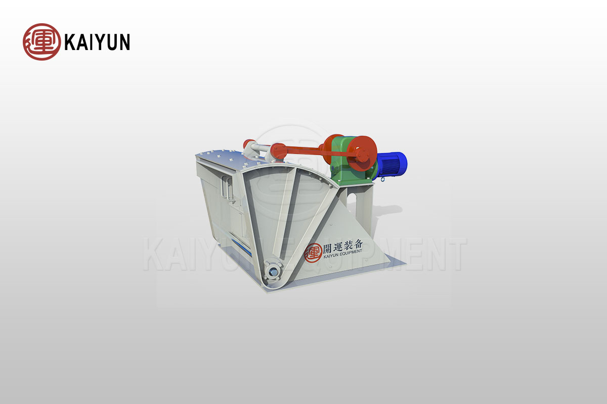
Product Introduction
The Pendulum Feeder, designed for periodic reciprocating feeding of fine materials, is a crucial auxiliary device in the field of transportation machinery.
Widely used in mineral processing plants, smelting factories, cement plants, sand mines, and mechanized casting workshops, it is suspended from steel structures and installed below hoppers.
This setup ensures continuous and uniform feeding of materials, contributing to the stability and efficiency of the production process.
Table of Contents

Advantages and Features
Compact Design and Reliable Sealing
The pendulum feeder utilizes a worm gear reducer as its core drive component, ensuring a compact structure. It is also equipped with a reliable sealing mechanism that effectively prevents dust leakage, maintaining a clean and safe working environment.
Versatility and Locking Function
When not in operation, the pendulum feeder can also function as a locking device, providing additional control over material storage and transport. This enhances the flexibility and practicality of the equipment.
Working Principle
The pendulum feeder operates based on its unique mechanical structure and drive mechanism. Typically installed beneath the discharge port of a hopper, the feeder receives material that falls naturally into the feed box from the hopper’s outlet.
During operation, an electric motor drives the worm gear reducer through a coupling, which then powers the eccentric wheel to drive the feed box’s swinging base in a reciprocating motion. This motion ensures even material feeding and continuous supply along the production line.
To accommodate various production needs, the pendulum feeder offers precise feed rate adjustment.
By modifying the scale on the eccentric disc of the eccentric wheel, the stroke of the eccentric wheel can be adjusted, thereby changing the swinging amplitude of the feed box and achieving accurate feed rate control.
Additionally, adjusting the speed of the variable-speed motor alters the number of swings, allowing for fine-tuning of the feed rate to ensure that material supply meets process requirements precisely.
Technical parameters
| Model | Feed port length*width (mm) | Discharge port length*width (mm) | Eccentric wheel stroke (mm) | Swing times (r/min) | Upper limit feed size (mm) | Feeding capacity (t/h) | Motor model | Motor power (kw) | Motor speed (r/min) | Weight (kg) |
| BG250*250 | 250*250 | 250*(30-125) | 0-90 | 46 | 25 | 4.5 | Y80L-4 | 0.55 | 1390 | 130 |
| BG300*300 | 300*300 | 300*(30-125) | 0-90 | 46 | 30 | 6.5 | Y802-4 | 0.75 | 1390 | 272 |
| BG400*400 | 400*400 | 400*(50-130) | 0-170 | 45.5 | 35 | 12 | Y90S-4 | 1.1 | 1410 | 558 |
| BG600*600 | 600*600 | 600*(50-150) | 0-157 | 48 | 50 | 40~80 | Y100L-4 | 1.5 | 940 | 613 |